Power line diagram what is the difference between transmission and
Table of Contents
Table of Contents
Are you interested in learning how to draw power circle diagrams of transmission lines? It might seem difficult, but with the right guidance, it’s not as daunting as it appears.
Understanding the basics of a transmission line’s electrical characteristics is essential in developing an effective power circle diagram of transmission line. The first step in the process is to understand the theoretical basis for the circle diagram.
The power circle diagram provides a comprehensive picture of the transmission line’s electrical characteristics. The power transmitted and received, voltage regulation, and efficiency of the system can all be analyzed with the help of a power circle diagram.
In this article, we will walk you through how to draw power circle diagrams of transmission lines in easy-to-understand language. By the end of this article, you’ll have a firm grasp of the process and the ability to create your own power circle diagrams with ease.
Understanding the Basics of a Power Circle Diagram of Transmission Line
Before we dive into how to draw power circle diagrams of transmission lines, let’s start with understanding the basics of a power circle diagram. A power circle diagram is a graphic representation of a transmission line’s characteristic in terms of power and voltage. The power circle diagram consists of three sections: electrical power input, losses, and electrical power output. The input represents the power source, while the output represents the load. The losses represent the power dissipated due to the resistive nature of the transmission line.
As an electrical engineer, I have experience creating power circle diagrams. The key takeaway from my experience is that you must comprehensively understand the transmission line’s characteristics before attempting to draw the power circle diagram.
Step-by-Step Guide on How to Draw Power Circle Diagrams of Transmission Lines
To draw a power circle diagram of a transmission line, you’ll need to follow these steps:
- Calculate the total power input
- Calculate the total power output
- Calculate the reactive power output
- Calculate the resistance and reactance of the transmission line
- Calculate the total transmission line impedance
- Draw the power circle diagram
It’s important to note that these are simplified steps, and there are many more details involved in each step. Nonetheless, this is the general process.
Calculating the Total Power Input
The first step in drawing a power circle diagram of a transmission line is to calculate the total power input. This is calculated using the following formula:
Total power input = Voltage x Current x Power Factor
It’s important to note that voltage is the voltage at the sending end of the transmission line, and current is the total current flowing through the transmission line.
Calculating the Total Power Output
The second step is to calculate the total power output. The formula for calculating the total power output is as follows:
Total power output = Voltage x Current x Power Factor
It’s important to note that voltage is the voltage at the receiving end of the transmission line, and current is the total current flowing through the transmission line.
Why is Power Circle Diagram of Transmission Line Important?
The power circle diagram is an essential tool in analyzing the performance of a transmission line. It provides a comprehensive visualization of the system and allows engineers to identify potential issues. By understanding the electrical characteristics of the system, engineers can make informed decisions regarding improvements and maintenance.
Drawback of Power Circle Diagram of Transmission Line
While the power circle diagram provides a comprehensive picture of the transmission line’s electrical characteristics, it does have a drawback. It assumes that the line’s impedance does not change with varying load conditions. However, this is not always the case, and changes in the line’s impedance can affect the power circle diagram’s accuracy.
Question and Answer
Q: What is the purpose of a power circle diagram?
A: The power circle diagram provides a comprehensive picture of the performance of a transmission line. It allows engineers to analyze the power transmitted, voltage regulation, and efficiency of the system.
Q: How is the total power input calculated?
A: The total power input is calculated using the formula: Total power input = Voltage x Current x Power Factor.
Q: What is the drawback of the power circle diagram?
A: The power circle diagram assumes that the impedance of the line does not change with varying load conditions. This can affect the accuracy of the diagram.
Q: What are the three sections of a power circle diagram?
A: The three sections of a power circle diagram are electrical power input, losses, and electrical power output.
Conclusion of How to Draw Power Circle Diagrams of Transmission Lines
Creating a power circle diagram of a transmission line requires a comprehensive understanding of the system’s electrical characteristics. By following the step-by-step guide outlined in this article, you can easily create a power circle diagram of a transmission line. Remember, the power circle diagram provides a comprehensive picture of the transmission line’s performance, allowing engineers to make informed decisions regarding maintenance and improvements.
Gallery
EEE COMMUNITY: Power Generation,Transmission,and Distribution By Smart

Photo Credit by: bing.com / transmission energy grids electricidad eee transformers lineman
Electrical Miracles: Construction Of Power Circle Diagram

Photo Credit by: bing.com / circle power diagram line construction horizontal ab
Receiving End Circle Diagram

Photo Credit by: bing.com /
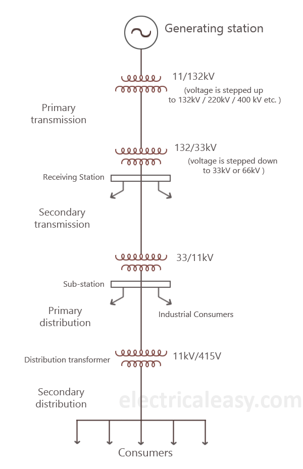
Basics Of Electrical Power Transmission System | Electricaleasy.com

Photo Credit by: bing.com / power system line transmission electric diagram single electrical ac load basics 11kv flow typical transformer energy kv notes generator dc
Power Line Diagram : What Is The Difference Between Transmission And

Photo Credit by: bing.com / engineering conductors electricaltechnology circuit powerlines apar sumitomo nexans ztt ctc players coronavirus


