Visio er diagram stencil download
Table of Contents
Table of Contents
Are you struggling with drawing entity-relationship diagrams in Visio 2007? Look no further! In this post, we’ll provide an in-depth guide on how to draw ER diagrams in Visio 2007 so you can create professional and functional database designs with ease.
Creating an ER diagram in Visio 2007 can be a daunting task, especially if you are not familiar with the software or if you have never created one before. However, with the right guidance and resources, you can quickly become proficient in drawing ER diagrams and make them an essential part of your database design toolkit.
Before we dive into the details, let’s answer the most common question: what is an ER diagram, and why is it essential?
An entity-relationship (ER) diagram is a visual representation of entities and their relationships to each other. It is a critical tool for database design as it helps to identify the relationships between different entities and ensure that your database structure is organized and efficient.
How to Draw ER Diagram in Visio 2007 – Target and Basic Steps
The main target of this post is to guide you through the basic steps of drawing an ER diagram in Visio 2007. The primary steps include:
- Open Visio 2007 and select the “Database Model Diagram” from the template category.
- Add Entities to your diagram by dragging and dropping them from the “Entity Relationship” toolbar or by using the keyboard shortcut “CTRL + SHIFT + T”.
- Define Attributes by double-clicking the entity or right-clicking the entity and selecting “Properties.” Under the “Columns” tab, click “Add” to create new attributes, and under “Data Types,” select the data type for your attribute (e.g., integer, string, etc.).
- Create Relationships by clicking on the “Relationship” button on the toolbar or using the keyboard shortcut “CTRL + R.” To create a relationship, select the parent entity first, then the child entity, and define the relationship type (e.g., one-to-one, one-to-many).
- Save and Export your ER diagram in various file formats, such as JPG, PNG, or PDF.
Personal Experience – Tips and Tricks for drawing ER diagrams in Visio 2007
Having used Visio 2007 to draw ER diagrams for over five years, I have discovered some tips and tricks that can help make your workflows more efficient and your designs more professional:
- Use keyboard shortcuts instead of the toolbar to speed up your work. For example, use “CTRL + SHIFT + T” to add an entity, “CTRL + SHIFT + A” to add an attribute, and “CTRL + R” to add a relationship.
- Always keep your diagrams organized and tidy. Don’t be afraid to use color coding and grouping to make your diagrams better organized and easier to read.
- If you are working on a complex project, add comment boxes to your entities and relationships to help explain complex relationships and business rules.
Advanced Tips for drawing ER diagrams in Visio 2007
If you’re looking to take your ER diagram designs to the next level, consider implementing some of these advanced tips:
- Use shapes and icons to represent entities visually. For example, use a book icon for a library entity and a shopping cart icon for a customer entity.
- Use a naming convention for your entities and attributes to keep them organized and clear. For example, prefix an entity with “tbl” to indicate that it is a table.
- Use subtypes and supertypes to represent inheritance relationships between entities. This technique is useful if you have several entities that share the same attributes.
Best Practices for drawing ER diagrams in Visio 2007
When drawing ER diagrams in Visio 2007, following these best practices will help ensure that your designs are well-organized, efficient, and easy to understand:
- Start by defining the business rules that govern your database design.
- Identify the entities that are involved and their relationships to each other.
- Make sure that you have defined all the necessary attributes for each entity.
- Create logical relationships between entities by defining primary and foreign keys and mapping relationships.
- Lastly, document your process thoroughly, including any assumptions and decisions you made during the design process, for future reference.
Common Mistakes to Avoid When Drawing ER Diagrams in Visio 2007
Here are some common mistakes to avoid when drawing ER diagrams in Visio 2007:
- Not following a naming convention for your entities and attributes.
- Over-complicating your diagrams with too much technical jargon.
- Forgetting to define all the necessary attributes for an entity.
- Making assumptions without first validating the data with subject-matter experts.
Question and Answer
Q: Can I use Visio 2007 to draw an ER diagram?
A: Yes, Visio 2007 comes with a pre-built “Database Model Diagram” template that you can use to create ER diagrams.
Q: What is the best way to organize my entities and attributes in Visio 2007?
A: Use color coding and grouping to keep your entities organized and tidy. For attributes, use a naming convention to keep them clear and understandable.
Q: How do I define relationships between entities in Visio 2007?
A: To create relationships, select the parent entity first, then the child entity, and use the “Define Relationship” dialog to set properties, such as the relationship type.
Q: Can I export my ER diagram from Visio 2007 to other file formats?
A: Yes, Visio 2007 supports exporting to various file formats, such as JPG, PNG, PDF, and others.
Conclusion of How to Draw ER Diagram in Visio 2007
Creating an ER diagram in Visio 2007 can be straightforward, provided you follow the basic steps, best practices, and avoid common mistakes. To improve your designs, consider implementing advanced techniques, such as using shapes, subtypes, and supertypes, and documenting your process thoroughly.
By following this guide and using Visio 2007’s built-in tools and templates, you can create professional and functional ER diagrams that help you visualize your database data and relationships clearly.
Gallery
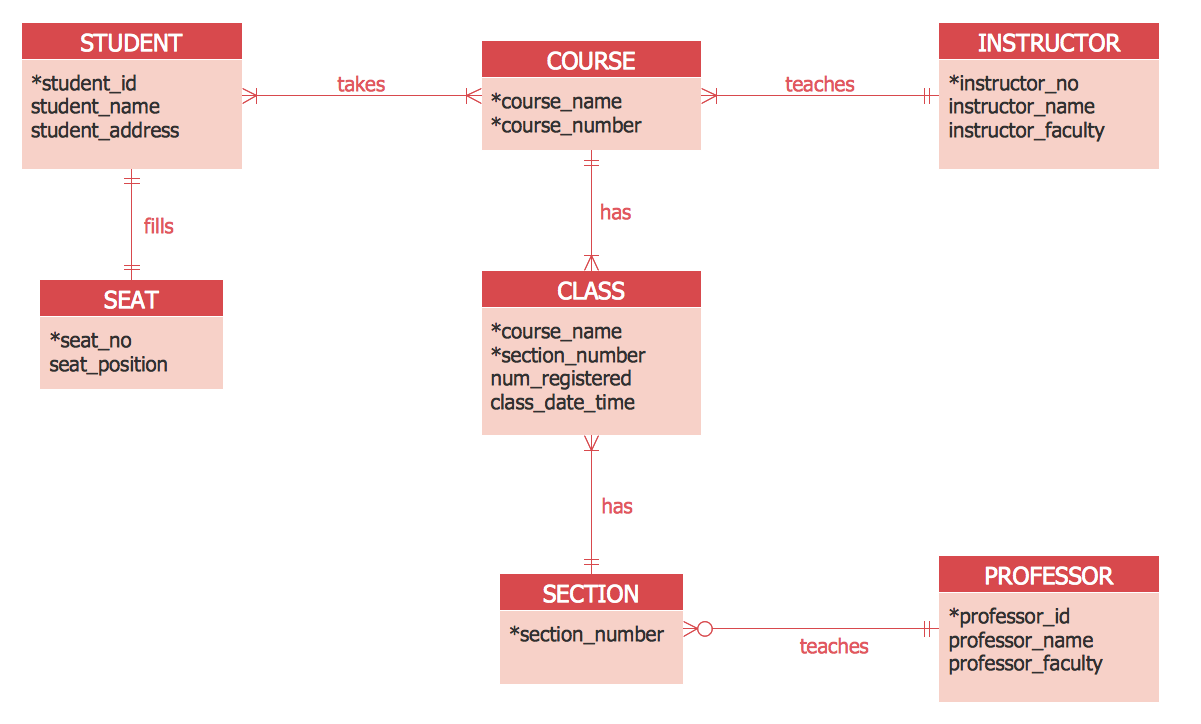
Create Er Diagram Visio - Free Wiring Diagram
Photo Credit by: bing.com / erd diagram foot er entity relationship notation software crows examples crow visio maker symbols diagrams create engineering database example professional
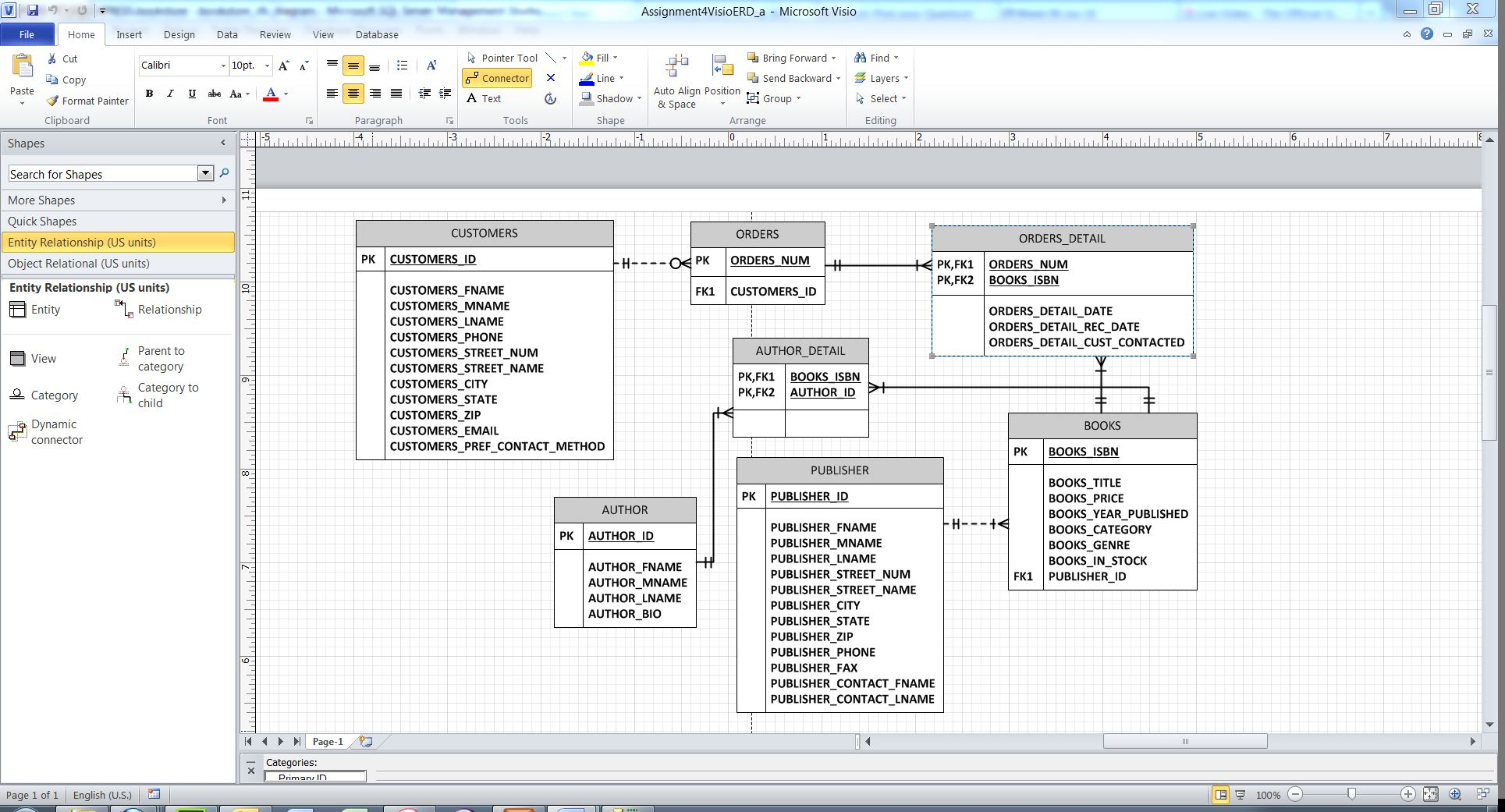
Entity Relationship Diagram Visio - General Wiring Diagram

Photo Credit by: bing.com / entity visio developed
Visio Er Diagram Stencil Download | ERModelExample.com

Photo Credit by: bing.com / visio entity membuat erd ermodelexample mudah
Entity Relationship Diagram Visio 2016

Photo Credit by: bing.com / erd entity foot notation visio crows crow cardinality scenario scenarios conceptdraw meanings flowchart solved ermodelexample explanation uml erds vector attribute
Er Diagram Visio Example – ERModelExample.com

Photo Credit by: bing.com / visio entity erd ermodelexample weak


